Marc Zeitlin
-
Posts
1,366 -
Joined
-
Last visited
-
Days Won
58
Content Type
Profiles
Articles
CSA Articles
CSA Issues
Forums
Blogs
Events
Gallery
Downloads
Store
Everything posted by Marc Zeitlin
-
Kent's Long-EZ project
Marc Zeitlin replied to Kent Ashton's topic in Builder Progress Reports & Motivation
Checked every CI :-). -
Kent's Long-EZ project
Marc Zeitlin replied to Kent Ashton's topic in Builder Progress Reports & Motivation
Funny you should mention this and post the second picture. While doing the CI on your Long-EZ for Ed two days ago, I noted that the #3 exhaust pipe (the one in the picture in the purple square) had a crack about 2/3 - 3/4 the way around the pipe on the second weld down from the bend. Luckily, Mike M. was at the hangar and was able to weld it up for us. -
Long EZ Aileron Torque Tube bearing replacements
Marc Zeitlin replied to cbretana's topic in Long-EZ
Nope. 0.049" wall, not 0.095" wall. 03-03700. It's in the plans... You may have to file/sand down the OD of the tube a thousandth or two to be able to slide easily into the bearing/bushing. You also want to make sure that you drill the bolt holes with a centering jig, and tighten both bolts to the point of JUST BARELY ovalizing the tubing so that it will have no play in it. -
These days, any wingtip lights I install are one of the 4 or 5 different LED NAV/STROBE/POS combination lights. They're all small, lightweight, bright, and expensive. Whichever one the customer picks. There's no structural or aerodynamic issue with any of the available lights. Landing lights are landing lights - they don't care what plane they're mounted on. I haven't done side by side comparisons so I don't know what beam angle is optimal for any plane. I used to have automotive driving lights on my plane, and they were barely adequate. I've just installed these: https://flyleds.com/products/#!/Single-Spotlight/p/108852015/category=0 one standard, one 30 degree beam. Haven't tried them at night yet, so no feedback. If you want to be night legal, you'll need to get a N/S/P light that meets the TSO requirements, even if they're not TSO'd. But getting specs on the non-TSO'd lights is like pulling teeth...
-
Long EZ Aileron Torque Tube bearing replacements
Marc Zeitlin replied to cbretana's topic in Long-EZ
The Triangle FMN10 nylon bearings have been commonly used and they're total crap. They have substantial play in them, sometimes right from the get-go, and they loosen up more over time. I wouldn't put them in a children's toy. They also have an iron version - the FM1510P, but I've never used them or seen them used and can't comment on them. The EFOI-10 bearing from IGUS is extremely high quality, low price, and would be what I would use if I were either replacing existing worn bearings or building new. -
Why would you post a COZY question in the Varieze forum? And we just had this exact discussion on the COZY mailing list...
-
Replied to you via email.
-
That's an interesting question. So few VE's have the cuffs at this point, and so few have the fences that there's no overlap between the two groups, to my knowledge. There's no reason the fences, which are installed both for aileron effectiveness at low speeds as well as some deep stall resistance margin, shouldn't work with the cuffs as they do with the vortilons. There are two versions of VG's for canard aircraft. The first (not mentioned in that ad for extremely expensive VG's that you can make yourself for $10) are : GU Canard trim change in rain eliminators These are installed on the canard ONLY, and far enough forward that they do NOT affect the maximum Cl that the GU canard can produce - they ONLY eliminate the change in pitch trim with contamination (rain, bugs, whatever else gets on the airfoil). The next version is the ones mentioned, that are installed on a different chord point on the canard, as well as on the main wing. These are installed to lower stall speed, and hence approach and landing speeds. On Long-EZ's, they were developed by Jim Price for his altitude record flights (he gained over 2K ft. of altitude due to the lower speed he could fly at with the VG's). You NEVER put the second version of the VG's on the canard alone, because then a deep stall is likely. And you don't put them on the main wing alone, because it won't accomplish anything. If one installs the second version of the VG's, expect to lose a couple of knots on the top end in exchange for the lower stall speed on the bottom end.
-
Stephen is correct here - CP-42, pages 5 and 6 have the information on using Vortilons on the leading edge instead of cuffs. They seem to indicate that the Vortilons hold some reasonable advantage over cuffs, but obviously the cuffs work well too. It's interesting that they indicate that there wasn't good data for installing Vortilons on the Long-EZ, but obviously at some later point, they changed their minds.
-
On the COZY MKIV, this is the case. On the Long-EZ Roncz canard, the original implementation did not have offsets, at least on the planes I've seen... I"m sure there are some folks that have implemented offsets like Nick Ugolini has.
-
This is exactly what Velocitys do on their elevator torque tube, since the elevator hinge points are well below the bottom of the canard on that plane as well.
-
Kent's Long-EZ project
Marc Zeitlin replied to Kent Ashton's topic in Builder Progress Reports & Motivation
Please quote accurately - that was NOT the COZY mailing list, that was the Canard Aviators mailing list. Don't get me started on why there are 57 thousand different places to get canard fixes... Good stories, though. -
The way I interpret that (and the way I inspect, although I use 0.060" as the minimum, not 0.080") is that as I move the LE of the aileron up and down, there should never be any time where the TE of the cove and the LE of the aileron come within 0.060" of one another. If they do, I sand the TE of the cove fwd so that there is enough clearance (generally, I slide a popsicle stick between the two to ensure enough clearance). The reason for the clearance is to avoid aileron lockup during high "G" turns - there have been instances where someone pulls 4 - 5 G's and then tries to roll out of it, but because of the bending of the wing (and the NON-bending of the aileron), the aileron sticks. The easy solution is to push and unload to get back down to 1G, but that's not always at top of mind during a 4G turn in which your ailerons have stopped working. So yeah - ensure that there's appropriate clearance at ANY position of the aileron LE.
-
Clean the inside surface of the cowl near the exhausts - completely free of grease and oil. Then sand it to scuff a bit. Then use Red High Temperature RTV as an adhesive, put a layer of 1/16" Fiberfrax over the area to be protected. Then cover the whole area with AL tape: https://www.aircraftspruce.com/catalog/cspages/3mproptape.php Then seal the edges of the tape with a bead of Red RTV. For what reason? What do you propose changing it in to?
-
Kent's Long-EZ project
Marc Zeitlin replied to Kent Ashton's topic in Builder Progress Reports & Motivation
I love those things - I get 350 - 375 landings out of a set - way more than the new tires, that cost more. They are not always available, though... -
Kent's Long-EZ project
Marc Zeitlin replied to Kent Ashton's topic in Builder Progress Reports & Motivation
Actually, a constant descent rate is still at 1G - the only time there is acceleration or deceleration vertically is if the descent RATE is changing. That's the definition of acceleration. So no matter what the descent angle is - 1 degree, 3 degrees, 10 degrees - if the descent RATE is constant (300 fpm, 500 fpm, 1000 fpm), you're still at 1G. Now, what MAY be going on in what you're feeling is a CHANGE of descent rate, and that's an acceleration, and that you CAN feel. But you can't feel velocity, and downward velocity does not imply a change of "G" loading. For this poor woman, what she probably didn't feel was the backside of the power curve increasing her descent RATE, and the wing stalling and slamming the nose gear into the ground. -
The first sentence is incorrect. The Varieze was the first implementation of the "Whitcomb" winglet, and Whitcomb's original design included the small lower winglet, so when Burt adopted the Whitcomb design, he included the lower winglet as well. As it turns out, unless you're cruising around at the Max. L/D speed (which we never do, because it's very slow or unless you're very high), it does, in fact, contribute little to aerodynamics. But the lower winglet was NOT put there as physical protection, but as an aerodynamic feature. With the anhedral in Varieze wings, runway contact of the lower winglet is not unknown, but is purely a cosmetic issue, as the lower winglet is not structural.
-
Not nearly enough information to make a recommendation. What prop is on the plane now? Do you have wheel pants? If so, what type? What RPM do you see static? What RPM do you see on the takeoff roll, just as you rotate? Is the 2350 RPM you mention what you've seen recommended, or what you actually get? What RPM do you currently see in cruise, and at what DA, throttle and mixture setting? What RPM do you see at WOT, leaned for max power, at what DA? What I like to see in an all-around climb/cruise propeller is the ability to exceed maximum engine RPM (which, for an O-200, is 2750 RPM) by 50 - 100 RPM when at WOT, leaned for max power, at your usual cruise altitudes (call it 8500 ft.). So in this case, you'd want to see 2800 - 2850 RPM (you won't hurt the engine) in those conditions. If you get less RPM than that, you've got more of a cruise prop, and if you get more RPM than that, you've got more of a climb prop. But these #'s will also be dependent on aircraft drag - no wheel pants will decrease cruise speed by ~120 KIAS and RPM by ~100. Also, if the prop is not matched to the airframe well, you can have good static but lousy cruise, or vice-versa. Everything is interrelated - without more information, no recommendation can be made.
-
I didn't realize that "dangling things" were a primary driver of aircraft selection - in MY view, form follows function, but to each his own.
-
With all due respect, you've decided on an airplane that doesn't fit the mission you've defined. That's backwards. Determine the mission (one or two people, 30 kg dog, some baggage, 1500 km range). THEN go find a plane that can fill that mission. I will tell you that if you're partial to canard planes, a COZY or Velocity will do it with no modifications whatsoever. If only ONE person and a dog, then a Long-EZ will fill the mission. Mission first, THEN airplane. There is no way to modify a Q2 to do what you're asking - stop thinking about it. For weight, CG, structural mods, fuel capacity - not going to happen.
-
First, I use the longest jobber drill I've got - maybe 2 ft, 3/8" dia. Then switch to AL tubing with teeth on the end. Doesn't work great - tends to tear the foam a bit and clog up easily. But I haven't found anything better, yet. No holes through primary structure. The hole I drill is from the area FWD of the LE of the winglet, where the lights will actually attach, aftward to the end of the aileron cove. Since there's no shear web in the outboard wing of a Varieze, the hole only goes through foam. I remove the aileron so that I can also drill from the aileron outboard, and pray to Cthulhu that the holes meet somewhere about 1/2 out.
-
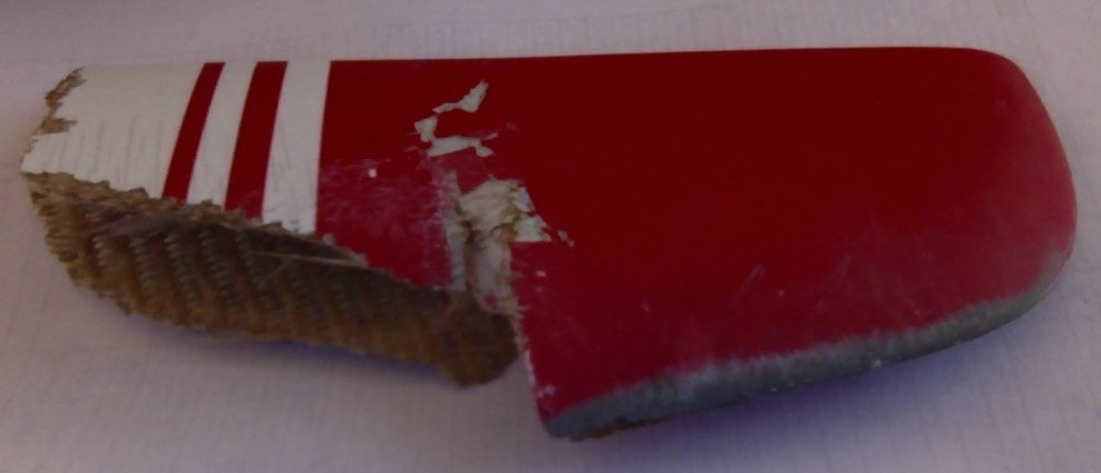
Ha. Picture's worth (in this case) 75 words. Interestingly, this (remove the section of the wing aft of the dotted red line): is what the TE of my right wing looked like after the prop hit it on its way to Joshua Tree NP 9500 ft. below us in 2006. The prop took off the TE outboard of the aileron, plus a little bit of the TE of the aileron over the last 4 - 6 inches. Plus 2/3 of the lower winglet. Left me with this: souvenir, stuck in what was left of the lower winglet. While I was mostly concentrating on other stuff at that point, I did not notice any substantial difference in the flight characteristics of the airplane on the way to the landing at Desert Center. When Mike Melvill flew me out to pick the plane up a few days later with a new prop and extension, as well as a bunch of AL tape, we taped up the TE of the wing to close out the exposed foam. It's called speed tape, right? He chased me home in the company Duchess, and I never went faster than 120 KIAS. Once again, there was no discernible difference in flight characteristics on the way home. After the flight, we ruminated on why anyone puts the last few inches of wing on the wing if it doesn't make any damn difference to how the airplane flies. But I fixed it back to the plans design anyway, not being an aerodynamicist :-).

-
Trailing edges should be neither rounded nor sharp. Both lead to vortex shedding, drag, and unstable airflow. You want the TE to be a flat squared-off surface, no less than 1/16" thick and no more than ~1/8" thick, ,although as you say many Lancairs have TE's with 1/4" thickness on the squared-off surface. This is particularly important (not to have a sharp TE) on the ailerons, so as not to affect control forces.
-
I've done it on two VE's. The hardest part is drilling a hole from the wingtip to the end of the aileron cove for the wiring without drilling through the top or bottom skins. Other than that, it's just running some wires and creating hard points in the wingtip for the LED lights to mount on to. 1/2 - 1 day's work, maybe. Landing Lights on VE's are more problematic, as there just really aren't many places to put them. A fold down one, like on the Long-EZ, could be done, or something like this: https://www.aircraftspruce.com/pages/el/landinglights_aveo/aveo_11-18453.php on the bottom of the fuselage, next to the nose gear wheel well.
-
SOLD: Cozy Mark IV Project For Sale
Marc Zeitlin replied to JKillin's topic in For Sale (or for Free)
C'mon, Cameron. Are we there yet? Are we there yet? Dad - are we there yet? When are we going to get there? Are we there yet?